

Proper component selection is critical to ensure the success of building a center-driven rewind stand. While many factors need to be taken into consideration, ultimately it is the quality of the wound roll that is of prime concern. Material advances have presented a host of challenges for machine designers to overcome to ensure proper wound roll quality. From lightweight, extensible films and non-wovens, to foils and even non-traditional materials, choosing the proper method and equipment can mean the difference between failure and success.
Clutches are not often chosen to control tension on center winders because their proper application and the advantages of using a clutch with a motor are usually not understood.
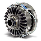
Montalvo CD Tension Clutch
Usually, when one finds a clutch-controlled center winder, the clutch is “geared in” to run 50 RPM faster than line speed at core. The clutch is usually driven by a constant RPM AC motor, and therein lays the crux of the problem.
As the diameter of the roll increases, the torque at the clutch must be increased proportionately to maintain a constant tension profile in the web. As the torque and roll diameter increase, the slip speed of the clutch also increases as a result of diameter increase.
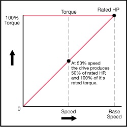
Most small Montalvo clutches, for their physical size, are capable of transmitting very high torque, however their limiting factor is their thermal dissipation. A good example of this can be seen with the Montalvo CD Series Clutch. The CD 136 equipped with 0.30 C.O.F. pads is capable of transmitting 885 lb.in. of torque at 75 PSI. Its maximum thermal capacity is, however, 2.4HP at 1750 RPM. Illustration A below shows the horsepower that a clutch must dissipate in a typical center winding application operated at a constant RPM. Please note: The dashed line illustrates the constant, (low) HP dissipation required of a CD 136 clutch when it is operated at a constant 50 RPM over-speed.
Illustration A
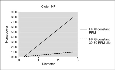
This clutch has the capability of transmitting the torque developed by a 20HP, 1750 RPM motor. The problem is that it cannot dissipate the 20 HP. However, if the clutch were driven by a variable speed motor, then by controlling the slip speed of the clutch and keeping it within the acceptable dissipation envelope, the CD 136 would make an excellent center wind tension transmitter. The motor would be geared in to operate 50 RPM faster than line speed in order to develop slip RPM at the core. As the roll diameter increases, the motor RPM is decreased to maintain same slip RPM. In Illustration A, the solid line illustrates the thermal HP the clutch would have to dissipate if the input is driven at constant RPM. The thermal capacity of the clutch would be exceeded at approximately 1/3 of the maximum diameter. The dashed line shows the HP dissipation if a 50-RPM slip is maintained throughout the wind. Dissipation is constant at 0.09 HP, which is well below maximum even at the slowest RPM. Note: Illustration “A”, dotted line indicates the 0.9HP!
The standard objection to this method is, “If I have to have a variable speed drive on the winder, I might as well use that to set my winder speed and tension, eliminating the clutch completely.”
This is not correct!
Here’s why:
A variable speed drive is just what its name suggests. What it does best is vary its output speed based on an input speed reference. It is not a tension transmitter. Most variable speed drives are constant torque/variable horsepower devices. They are not natural tension transmission devices – they set speed. In order to use a variable speed drive to set tension, there are three ways to go:
1. Use a dancer to set web tension. The dancer controls the speed of the drive. However, a dancer does not directly control web tension, nor does it give the operator tension readout.
2. Use a load cell-based tension control to trim 5 to 10% of the speed reference circuit.
3. Current control a DC motor, thereby making it a variable torque/variable horsepower device. However, used in this configuration, a motor is very sluggish and slow to accelerate, usually requiring a “kicker circuit” to get it started. When starting up at core, the motor must accelerate rapidly from zero RPM to near maximum in order to wind the material being fed from the process. This is exacerbated by the relatively high inertia of the motor armature compared to that of the clutch! A clutch, because of its inherent design and low inertia produces a “Soft Wind”. A drive and it’s associated inertia and inherent design produces a “Hard Wind”! Although electronic intervention is often used to attempt to soften a drive and gearing winder, only, it can never achieve the “Soft Wind” that a clutch is capable of producing.
Both 1 and 2 are speed control modes, 3 is a tension control mode.
The formula for horsepower calculations for a center winder is expressed as:
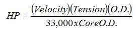
If the formula for roll buildup factor (O.D. & I.D.) is removed, you arrive at a formula for web or strip horsepower, thus:
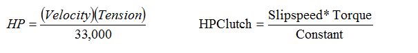
This is the formula that is used to size a motor for a surface winder, where the torque is always imparted to the web at the roll surface and not at the center of the roll.
All center winder drives that are rated as constant torque/variable HP drives are represented by the following graph:
If you calculate the strip HP to be 1 HP, and you have a 10:1 buildup ratio, you would need a 10 HP motor and drive. This holds true for either direct torque control of the motor, or for a clutch with a variable speed input. Sophisticated motor controllers, AC or DC, can make it possible to run with a 100Hz or field weakening, allowing one to reduce the motor size to half, in this case to 5 HP. However, if processing thin films or very light tension profile webs, another problem is introduced by operating the motor at very high RPM through field weakening or a high frequency in the case of a AC VFD. We have gained more HP by using a smaller size motor, (5 HP), and operating at twice it’s base speed! One needs now to provide a large gear reduction ratio to reduce the high RPM to the max RPM required at the winder input shaft! This introduces stored inertias, (similar to a flywheel effect), gear ratio inefficiency, etc., at the wind-up shaft. By inserting a small, low inertia clutch between the wind-up shaft and the winder drive train, one has isolated the winding function from the driving function and from the many variables that
would be transmitted to the web being wound! A small clutch will make a large change in output torque in approximately 40 milliseconds or less!
In spite of the slight additional complexity of adding a clutch to a rewind, the benefits are far greater, especially when running inextensible materials at light tensions. Inextensible products cannot tolerate large tension swings without damage or breaking. At start up, the clutch input is already running at line speed plus 50 RPM’s Only the rewind shaft, core and clutch spider have to accelerate up to speed. For direct torque control of a motor, the inertia of motor armature and gearing must also be accelerated. Throughout the winding process, a pneumatic clutch will always be more responsive than a drive to speed and tension changes.
For unwind applications the above benefits are the same, and in low tension applications it’s ideal that the clutch is running with reversed rpm. On machine stops it will hold a constant low tension. This solution is used by the hundreds on multiple die-cutters and laminators, with up to 10 unwinds/rewinds per machine, for producing mobile telephone components. This system is superior to AC/DC and servo drives, eliminating the dancer by using load cells only.
All winding shafts in this multiple machine can be used as unwind or rewind by reversing the input rpm to the clutch.
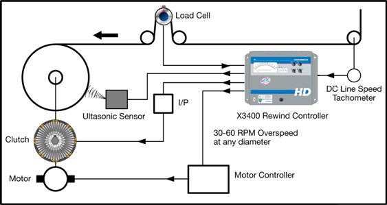
The best solution is to control the clutch and the web tension using a load cell and the Montalvo’s Rewind Tension Controller, the Z4-RL, formerly the X-3400. A line speed reference is connected to the tension controller. The Z4-RL then outputs a 50-RPM over-speed at core to the variable speed drive. As the roll diameter increases, the Z4-RL decreases the speed reference to the drive in order to maintain a constant slip RPM and therefore a constant slip horsepower.
The controller can calculate roll diameter based on pulses from two proximity switches or from a diameter input from an ultrasonic sensor. Alternatively, it can use an analog diameter from the machine PLC.
In conclusion, superior results when winding just about any material can be achieved with relative simplicity. All that is needed is a clear understanding of what can be accomplished with a motor and clutch.
© Montalvo – Permission granted to use this copyrighted material, in part or all, provided that the source is acknowledged as © www.montalvo.com