Industrial control systems are engineered and designed to provide control, process monitoring, and functions in manufacturing facilities. Control loop systems are implemented within industrial control systems to ensure the desired processes and functions are achieved. Consisting of numerous components, control loop systems utilize programmable software to command the many variables throughout industrial processes in order to meet manufacturing output. Each component in the control loop system works in conjunction to manage the industrial process.
What is a Control Loop?
Control loop systems monitor and regulate the devices, instrumentation, and machines used in industrial or manufacturing processes. The system operates hardware components and software control functions necessary to measure and adjust the variables that affect each process. Consider control loop systems as a process management tool designed to maintain the process variable at a desired set point each step of the way. Process variables are a set of programmable parameters that monitor and control a process to ensure that the output is maintained within a given limit or quantity. Control loop components and instrumentation first measure the variable, respond to it, and then control the variable to maintain it within a set limit.
Control Loop Systems
There are two common control loop systems used in industrial processes. They are the open loop system and the closed loop system. The systems are distinguished by the control actions.
Open-Loop Systems
 In an open-loop control system, control actions are independent of the desired output, meaning that the output is not measured or fed back to the input for comparison. Once an input command is applied to a controller it produces an actuating signal. This controlling signal is given as an input to a process which is to be controlled and thus produces a desired output. Essentially, without a feedback system in place, open loop systems operate without any checks and balances and are expected to follow its input command regardless of the final result.
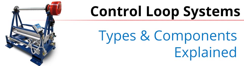
In a tension control open-loop system there are three primary elements: the controller, the torque device (brake, clutch, or drive), and the feedback sensor. The feedback sensor commonly is focused on providing diameter feedback and the process is controlled proportionally to the diameter signal (as opposed to continuous measurement based on direct web feedback like in closed loop systems). As the sensor measures the changes in diameter and relays this signal to the controller, the controller proportionally regulates the torque of the brake, clutch, or drive to maintain tension.
Closed Loop Systems
In a closed loop control system, the control action from the controller is entirely dependent on the desired output. It is fed back through to the input to control the action of the desired output.
Closed loop systems measure, monitor and control the process through feedback to compare the actual output with the desired output. In doing so it greatly reduces error and brings about the desired output or response.
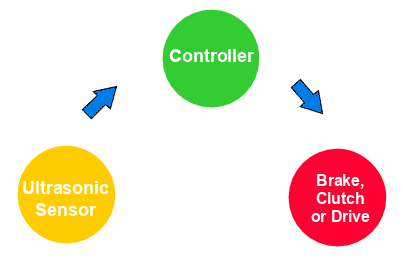
In a tension control closed-loop system there are four primary elements: the controller, the torque device (brake, clutch, or drive), the tension measurement device, and the measurement signal. The controller receives direct material measurement feedback from the load cell or dancer arm. As tension changes, it produces an electrical signal that the controller interprets in relation to set tension. The controller then regulars the torque of the torque output device to maintain the desired setpoint.
Control Loop Components
Primary Sensor
Depending on the process, primary sensors are a major component of control loop processes. Sensors supply signals proportional to process variables, such as diameter, dancer position, speed, etc., and measure any change required for a control loop. This information is tied back into the controller to produce finer levels of control.
Load Cell
Load Cells used with moving webs are devices that measure the force applied by the material as a result of micro-deflections of the idler roller they are attached to, caused from tension tightening or loosening as the material travels through the process. This measurement is in the form of an electrical signal (often millivolts) that is sent to the controller for interpretation and utilization in regulating torque to maintain set tension.
Converter
Converters are electro-mechanical devices used for converting electrical energy from the controller to the energy type required to control the torque device. They can be used to convert electrical energy into a pneumatic output, such as an IP Converter, or electrical energy into a DC Voltage for control of motors and magnetic particle torque devices, such as an E/V Converter.
IP Converters & Voltage Converters
Indicator
Indicators are devices that provide a readable indication of an instrument signal in automation and industrial instrumentation systems.
Recorder
Recorders are devices that log data acquisition. They are used to record measurement data over a given time period. When integrated into industrial control systems the device measures the history of processes and can be submitted for regulatory oversight or monitoring.
Controller
Controllers are integral components in process control systems. The device is responsible for the performance and function of the control system that works to maintain the value of the process variable at set point.
Actuator
An actuator is a component of a machine that is part of the correcting element responsible for moving and controlling a mechanism or system when it receives a control signal. The actuator converts a signal’s energy into mechanical motion, such as opening a valve.