

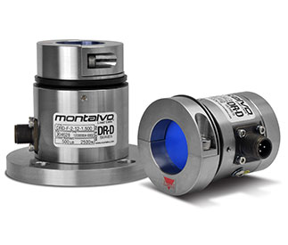
As alternatives to DFE Model C dead shaft style tension transducers, Montalvo’s DR-D Series feature integrated 3-pin connectors while meeting DFE product dimension specifications.
U.S.: 1-800-226-8710
Germany: +49 (0)511-760 691 41
Direct Replacements
DR-D load cells meet DFE product dimension specifications to easily drop into to your existing application without any work or process interruption.
3 Pin Connector
Integrated 3 pin connector allows for matching existing wiring configurations.
Stainless Steel
A 100% Stainless Steel body & dust proof (IP54) rating makes the DR-D Dead Shaft/Idler load cells more durable and more rugged for an extended, dependable service life.
Industry Leading Resolution
DR-D 3 Pin Load Cells lead the industry in resolution & sensitivity. No one makes a better load cell.
Multiple Mounting Options
Standard, and Flange mounts available, while also being able to easily integrate into existing Pillow Block Mounts
Quality, Service, Support
Like all of our products, the DR-D’s are backed by Montalvo’s leading quality, service, and support. We are here for you!
Mechanical Variance Compensation
Unique design compensates for shaft expansion & misalignment so performance is never sacrificed in the event of small installation variables.
360° Overload Protection
DR-D Dead Shaft/Idler Load Cells feature 300% overload protection from any angle. Montalvo keeps your load cells protected & your machines running.
Meets Your Requirements
Multiple load ratings, and three different body sizes to meet the specific needs of your application.
For additional information on the DR-D Dead Shaft-Idler Load Cell download the Datasheet.
Mounts via a single screw in the rear center of the back of the load cell, typically between machine frames where application forces are 500 lb (2225 N) or less.
Size 0 (shaft ends up to ø 1.5 inches max.)
DR-D Standard Mount Size 0 is the alternative to DFE’s C-0-D-S.
| Model | Load Range – lbs (N) | Max. Shaft ø in (mm) | Price |
|---|---|---|---|
| DR-D-S0-25 | 2.5 (12.5) – 25 (125) | 1.5 (40) | Price Request |
| DR-D-S0-50 | 5 (25) – 50 (250) | 1.5 (40) | Price Request |
| DR-D-S0-75 | 7.5 (37.5) – 75 (375) | 1.5 (40) | Price Request |
| DR-D-S0-100 | 10 (44.5) – 100 (445) | 1.5 (40) | Price Request |
| DR-D-S0-150 | 15 (75) – 150 (750) | 1.5 (40) | Price Request |
Size 1 (shaft ends up to ø 1.5 inches max.)
DR-D Standard Mount Size 1 is the alternative to DFE’s C-1-D-S.
| Model | Load Range – lbs (N) | Max. Shaft ø in (mm) | Price |
|---|---|---|---|
| DR-D-S1-100 | 10 (44.5) – 100 (445) | 1.5 (40) | Price Request |
| DR-D-S1-150 | 15 (75) – 150 (750) | 1.5 (40) | Price Request |
| DR-D-S1-250 | 25 (125) – 250 (1250) | 1.5 (40) | Price Request |
Size 2 (shaft ends up to ø 1.75 inches max.)
DR-D Standard Mount Size 2 is the alternative to DFE’s C-2-D-S.
Drawings
PDF STEP
| Model | Load Range – lbs (N) | Max. Shaft ø in (mm) | Price |
|---|---|---|---|
| DR-D-S2-75 | 7.5 (37.5) – 75 (375) | 1.75 (40) | Price Request |
| DR-D-S2-100 | 10 (44.5) – 100 (445) | 1.75 (40) | Price Request |
| DR-D-S2-150 | 15 (75) – 150 (750) | 1.75 (40) | Price Request |
| DR-D-S2-250 | 25 (125) – 250 (1250) | 1.75 (40) | Price Request |
| DR-D-S2-500 | 50 (250) – 500 (2500) | 1.75 (40) | Price Request |
Mounts to a machine frame via a 4 bolt flange collar. This mounting style may also be required when application forces exceed the capacity of the Standard Mounting Style.
Size 0 (shaft ends up to ø 1.5 inches max.)
DR-D Flange Mount Size 0 is the alternative to DFE’s C-0-D-FL.
| Model | Load Range – lbs (N) | Max. Shaft ø in (mm) | Price |
|---|---|---|---|
| DR-D-F0-10 | 1 (5) – 10 (50) | 1.5 (40) | Price Request |
| DR-D-F0-25 | 2.5 (12.5) – 25 (125) | 1.5 (40) | Price Request |
| DR-D-F0-50 | 5 (25) – 50 (250) | 1.5 (40) | Price Request |
| DR-D-F0-75 | 7.5 (37.5) – 75 (375) | 1.5 (40) | Price Request |
| DR-D-F0-100 | 10 (44.5) – 100 (445) | 1.5 (40) | Price Request |
| DR-D-F0-150 | 15 (75) – 150 (750) | 1.5 (40) | Price Request |
Size 1 (shaft ends up to ø 1.5 inches max.)
DR-D Flange Mount Size 1 is the alternative to DFE’s C-1-D-FL.
| Model | Load Range – lbs (N) | Max. Shaft ø in (mm) | Price |
|---|---|---|---|
| DR-D-F1-100 | 10 (44.5) – 100 (445) | 1.5 (40) | Price Request |
| DR-D-F1-150 | 15 (75) – 150 (750) | 1.5 (40) | Price Request |
| DR-D-F1-250 | 25 (125) – 250 (1250) | 1.5 (40) | Price Request |
Size 2 (shaft ends up to ø 1.75 inches max.)
DR-D Flange Mount Size 2 is the alternative to DFE’s C-2-D-FL.
| Model | Load Range – lbs (N) | Max. Shaft ø in (mm) | Price |
|---|---|---|---|
| DR-D-F2-75 | 7.5 (37.5) – 75 (375) | 1.75 (40) | Price Request |
| DR-D-F2-100 | 10 (44.5) – 100 (445) | 1.75 (40) | Price Request |
| DR-D-F2-150 | 15 (75) – 150 (750) | 1.75 (40) | Price Request |
| DR-D-F2-250 | 25 (125) – 250 (1250) | 1.75 (40) | Price Request |
| DR-D-F2-500 | 50 (250) – 500 (2500) | 1.75 (40) | Price Request |
| DR-D-F2-1000 | 100 (500) – 1,000 (5000) | 1.75 (40) | Price Request |
*DR-D Load Cells are designed to fit within existing pillow block mounts. If you require a new pillow block mount, please Request
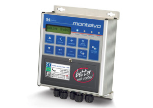
S4 Digital Tension Controller
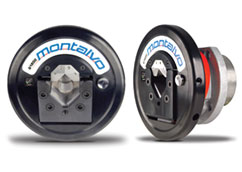
Guardian Safety Chucks
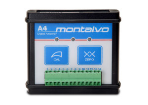
A4 Amplifier