

Downloads, FAQ’s and more.
*for drawings please visit the M3324 Amplifier product page
U.S.: 1-800-226-8710
Germany: +49 (0)511-760 691 41
Downloads, FAQ’s and more.
*for drawings please visit the M3324 Amplifier product page
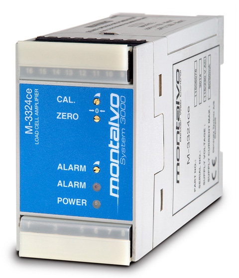
The Dip Switches are located under the side panel and can be accessed by prying up the side cover with a flat-bladed screwdriver. The dip switch settings determine the type and range of output on the two output terminals. The factory settings provide for 0 to 100 micro-amps of output on Terminal 13, and 4-20 mA output on Terminal 14. Terminal 12 can be configured for the 0-100 micro-amp or 0-10 VDC output, and Terminal 14 can be configured for 4-20 mA, 0-20 mA, or 0-10 VDC. The switch position is easily changed by sliding the proper switch into its appropriate position using a small, flat-blade screwdriver.
The M3324 is for use with load cells utilizing “Foil-Gage” technology, requiring 10 VDC excitation voltage. This differs from the M3224, which is primarily used with load cells utilizing ‘Strain-Gage” technology, requiring 5 VDC excitation voltage. The only difference is the load cell supply voltage. All other functions are the same.
Check the load cell supply output by measuring with a DC Voltmeter between terminals 9 (+5.0 VDC) and 15 (GND), and terminals 12 (-5.0 VDC) and 15 (GND). Next, measure between terminals 14 (+) and 15 (-), and adjust the zero pot until the meter reads 0.0 VDC. (*note* the dip switches must be positioned to ensure 0-10VDC on terminal 14. See note below, or M3324 Installation Sheet for procedure for changing dip switch position for proper output ranges). Now with the voltmeter still between terminals 14 and 15, adjust the CAL potentiometer and watch the meter. Turning the CAL potentiometer clockwise should cause the output voltage to increase. Turning it counter-clockwise should cause the output to decrease. This verifies that the output circuit is operating correctly.
The M3324 Amplifier is designed to be mounted on DIN rail. The unit can be supplied with a piece upon request at no additional charge. Mount the DIN rail in a dry, vibration-free area, where the ambient temperature does not exceed 100-degrees F. The amplifier simply snaps onto the DIN rail by hooking the top edge of the DIN rail slot on the upper edge of the rail, and pressing down until the spring-loaded clip “snaps” into place on the lower half of the rail. Removal is accomplished by inserting a flat-bladed screwdriver into the slot in the lower aluminum mounting clip, then rotating the screwdriver in either direction until the lower clip is released from the lower edge of the DIN rail. Gently pull up on the amplifier body to release the unit from the DIN rail completely.
Please note that the wire connection terminals can be removed as a unit to facilitate changing Amplifier Modules in the unlikely event that one should need to be replaced. Simply lift up the terminal block protective plate and gently pull the entire terminal strip straight out of the module. Both the upper and lower terminal strips can be removed in this fashion. A new module can now be snapped onto the DIN rail and the connectors re-attached.